
Agricultural Tractor Electrical System: Diagram, Connections, and Used Parts
The electrical system of an agricultural tractor is an interconnected set of circuits that governs starting, battery charging, and the operation of all onboard equipment. For John Deere, New Holland, Case IH, Massey Ferguson, Fendt, Deutz-Fahr, or Claas tractors, understanding the electrical diagram and the role of each component is essential for diagnosing faults, making connections, or planning replacements.
What Is the Electrical System of an Agricultural Tractor?
The electrical diagram of an agricultural tractor is based on a 12-volt direct current circuit. What type of energy does the tractor use? The engine runs on diesel, but all electrical systems—starting, charging, lighting, hydraulic controls, and onboard electronics—depend on a low-voltage electrical network powered by a lead-acid battery and maintained by an alternator.
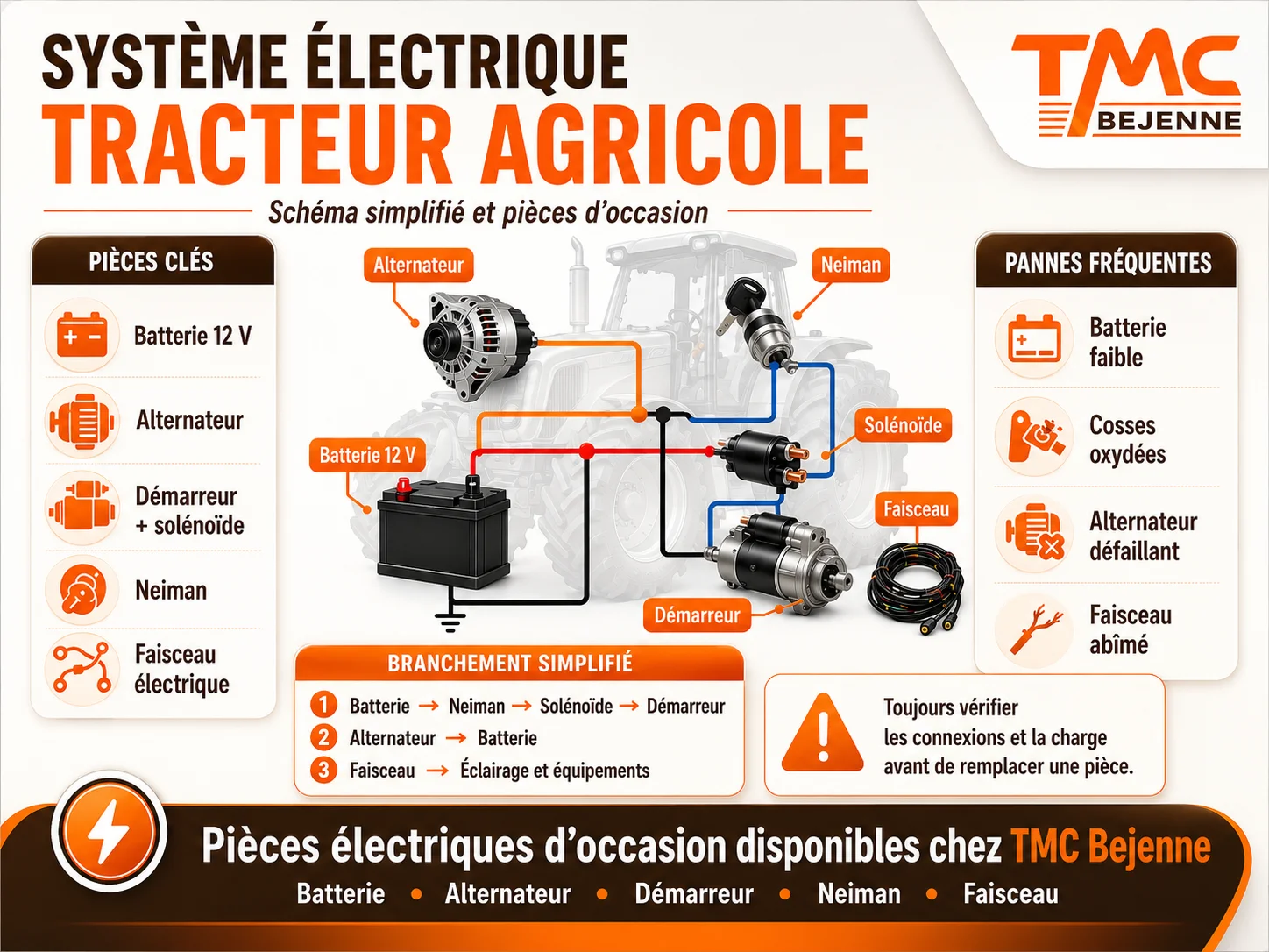
The circuit is divided into several sub-systems: the starting circuit (battery, ignition switch, starter solenoid, starter motor), the battery charging circuit (alternator, voltage regulator, battery), auxiliary circuits (lighting, hydraulic systems, power take-off), and the wiring harness that connects everything. Modern tractors also include electronic control units and sensors added to this basic diagram.
What Are the Electrical Components of an Agricultural Tractor?
The electrical circuit of an agricultural tractor includes the following components:
- Battery: stores the electrical energy needed for starting and powers engine electrical equipment when off. Battery capacity and voltage (12 V on common agricultural tractors) determine the available starting power.
- Alternators: continuously recharge the battery while the engine runs. High-performance alternators on modern tractors also supply power to onboard electronic equipment.
- Voltage Regulators: maintain charging voltage within acceptable limits to protect the battery and electrical components.
- Cables and Wiring Harness: cable harnesses connect all components. The quality of wires and condition of connections determine the reliability of the entire circuit.
- Glow Plugs: present on diesel engines, they facilitate cold starts by preheating the combustion chamber.
- Ignition Switch and Starter Relay: switch power circuits during engine start-up.
Tractor Starter Wiring: Operation and Starter Solenoid
The starter is a high-power electric motor that mechanically turns the combustion engine during starting. It is powered directly from the battery via a starter solenoid (or electromagnetic switch).
The solenoid wiring diagram follows this principle: when the ignition switch (#Neiman#) is turned to the start position, it sends a low-intensity signal to the solenoid. The solenoid then closes a high-current circuit between the battery and starter motor, enabling engine cranking. This two-stage circuit—low current control / high current power—protects the starter relay from premature wear.
Common faults on this circuit include: defective solenoid (clicking noise without engine start), corroded battery connections (voltage drop under load), or worn starter (slow or no engagement). On Massey Ferguson or Renault tractors, these faults often occur after winter storage. TMC Bejenne offers tested used tractor starters for major agricultural brands.
Ignition Switch Wiring on Agricultural Tractors: Key Switch and Starting Circuit
The ignition switch (#Neiman#) is the tractor's key-operated controller. It manages several circuits depending on the key position: powering electrical equipment, glow plugs, and starting. On agricultural tractors, ignition switches typically have 4 or 5 pins depending on the features included.
Key points for ignition switch wiring on agricultural tractors:
- Position 0 (Off): all circuits are off, except sometimes the parking lights.
- Position 1 (Run): powers all electrical equipment and control systems.
- Position 2 (Preheat): powers glow plugs on diesel engines.
- Position 3 (Start): sends the activation signal to the starter solenoid.
The 5-pin ignition switch wiring follows a standardized scheme on most agricultural tractors, but specific wiring varies by manufacturer. A starting switch wiring for a Massey Ferguson will not be identical to that of a Case IH: always consult the electrical diagram specific to your model before any work.
Tractor Alternator Wiring: Battery Charging Circuit
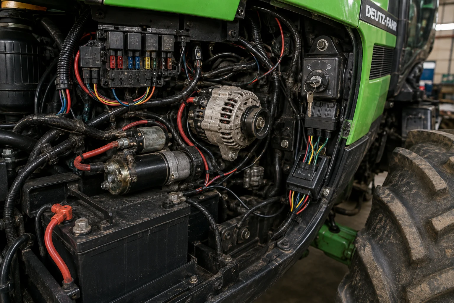
The alternator is the tractor’s electrical generator. It converts the engine’s mechanical energy into alternating current, then the built-in voltage regulator converts it to 12 V direct current to recharge the battery and power electrical circuits.
The battery charging circuit includes the alternator, voltage regulator (built-in or external depending on generation), wiring cables to the battery, and the line protection fuse. The tractor alternator wiring follows a simple scheme: the B+ terminal connects the alternator to the battery via a heavy-gauge cable, the D+ (or IG) terminal receives the start excitation signal from the ignition switch (#Neiman#). Older tractors with dual circuit alternators have slightly different wiring.
Common issues include: worn alternator (battery progressively discharges), faulty voltage regulator (overcharge or undercharge of battery), or corroded cables (voltage drop). Used tractor alternators inspected and available at TMC Bejenne for major brands.
Agricultural Tractor Wiring Harness: Cables and Circuits to Inspect
The wiring harness is the set of cable assemblies that connect all electrical components of the tractor. On older tractors or after long use, it often causes difficult-to-locate faults.
Priority inspection points on the agricultural tractor wiring harness:
- Main power cables: battery to starter cable and ground cable. Poorly secured or corroded ground cables cause voltage drops throughout the circuit.
- Connectors and terminals: oxidation of connections is the main cause of poor contacts. Clean and tighten terminals systematically before winter storage.
- Protective sleeves and insulation: cracked sleeves expose wires, promoting short circuits. Pay special attention to areas subject to abrasion (bell housing passages, joints).
- Fuses: check the condition and rating of each fuse. Replacing a fuse with a higher-rated one often hides underlying wiring faults.
The Renault wiring harness is particularly prone to aging in the 80s-90s series, as is the New Holland harness on T series. Used wiring harnesses are available at TMC Bejenne for the most popular models.
Electrical Diagrams and Used Parts at TMC Bejenne
Since 1945, TMC Bejenne has maintained a large stock of used electrical components from dismantled, workshop-checked agricultural tractors: starters, alternators, ignition switches (#Neiman#), wiring harnesses, voltage regulators, glow plugs, sensors, and switches for leading market brands.
Whether you need parts to rebuild the electrical diagram of a Massey Ferguson 140, to replace the harness on a Renault, or an alternator on a New Holland, our specialized technicians identify the compatible part for your model. Over 25,000 references permanently in stock. Contact our team at 05 86 24 00 26.
The electrical system of an agricultural tractor operates on a 12 V direct current circuit. It includes the lead-acid battery, the alternator responsible for charging, the ignition switch (#Neiman#) as the main controller, the starter for engine cranking, the starter solenoid, voltage regulators, wiring harness, and auxiliary circuits (lighting, sensors, hydraulic controls). Modern tractors also use electronic control units to manage engine systems.
An agricultural tractor runs on a diesel engine that mechanically drives the wheels via the transmission. Electrical energy from the battery and alternator powers the starter and all electrical equipment. The power take-off transmits power to attached implements. On modern tractors, hydraulic systems and electrical circuits control lifting functions, engine management, and onboard assistance features.
On a Massey Ferguson, the starter switch follows the classic 4 or 5-pin wiring scheme: permanent battery power (30), accessory power (15), starter output to solenoid (50), and depending on model, glow plug terminal (19) and ground terminal. Always consult the specific electrical diagram for your series before any work. To identify compatible parts, contact TMC Bejenne at 05 86 24 00 26.